|
|
|
|
|
|
|
|---|---|---|---|---|---|
|
|
|
|
|
|
|
|
|
|
|
|
|
|
|||
|---|---|---|---|---|---|---|---|---|
|
|
|
|
|
|
|
|||
| CNC1508-R33M | 0.33 | 0.55 | 0.65 | - | 105 | - | 66 | 55 |
1. All electrical specifications are referenced to 25°C ± 5°C ambient.
2. The inductance is measured at 1 MHz, 0.25Vrms, 0 ADC.
3. DCR measured on a micro-ohmmeter.
4. Isat, saturation current, means DC current at 25°C that causes an initial inductance drop of 30% approx.
5. Irms, temperature rise current, means DC current at 25°C that causes a temperature rise of 40°C approx.
Temperature rise is highly dependent on many factors including PCB land pattern, trace size, and proximity to other components.
Therefore temperature rise should be verified in application conditions.
6. SRF measured using WK6500B or equivalent.
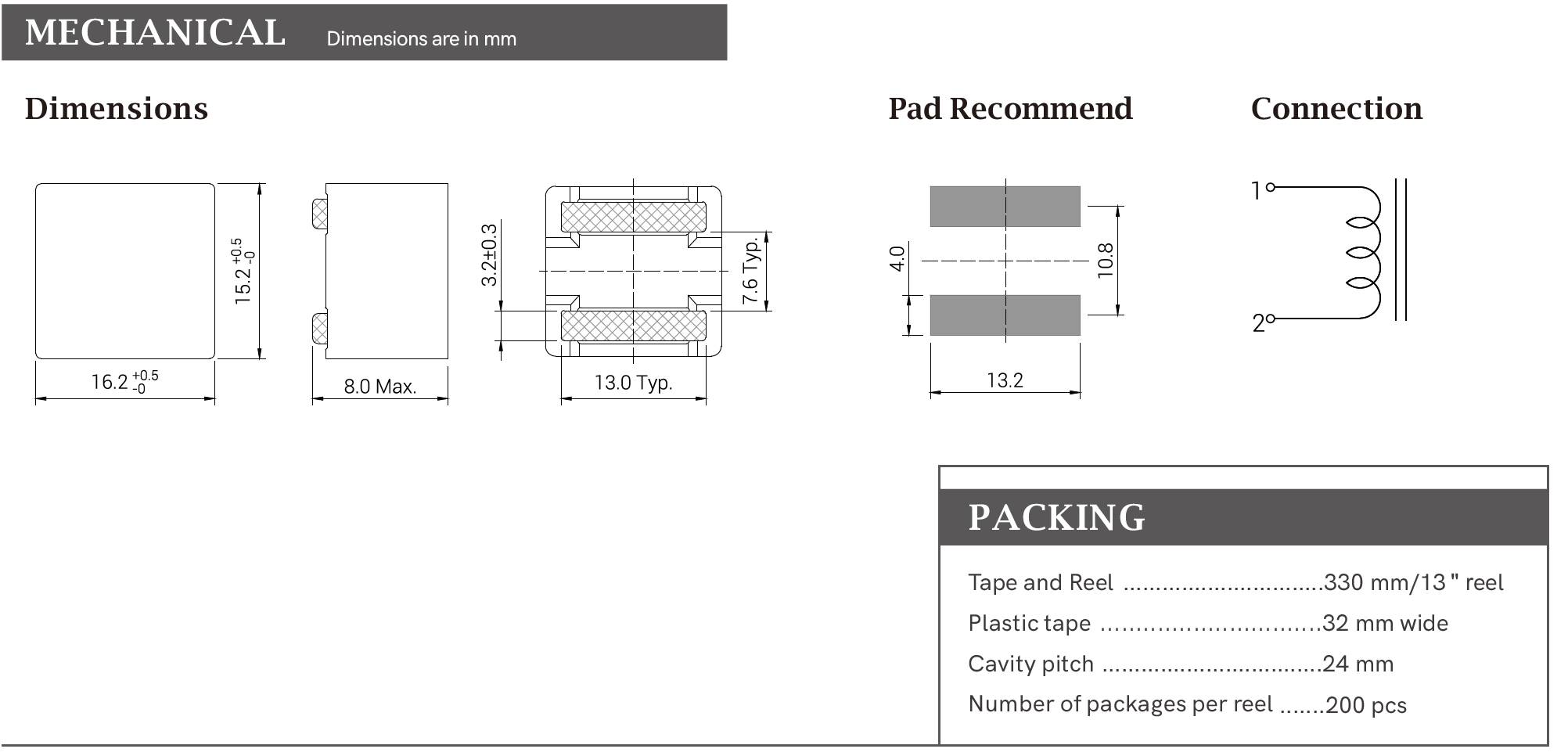
7. When it is being mounted on PWB, it is recommended to apply additional adhesive on the PWB to help hold the component more stable,
and the location applying adhesive should be in the middle of the two legs.
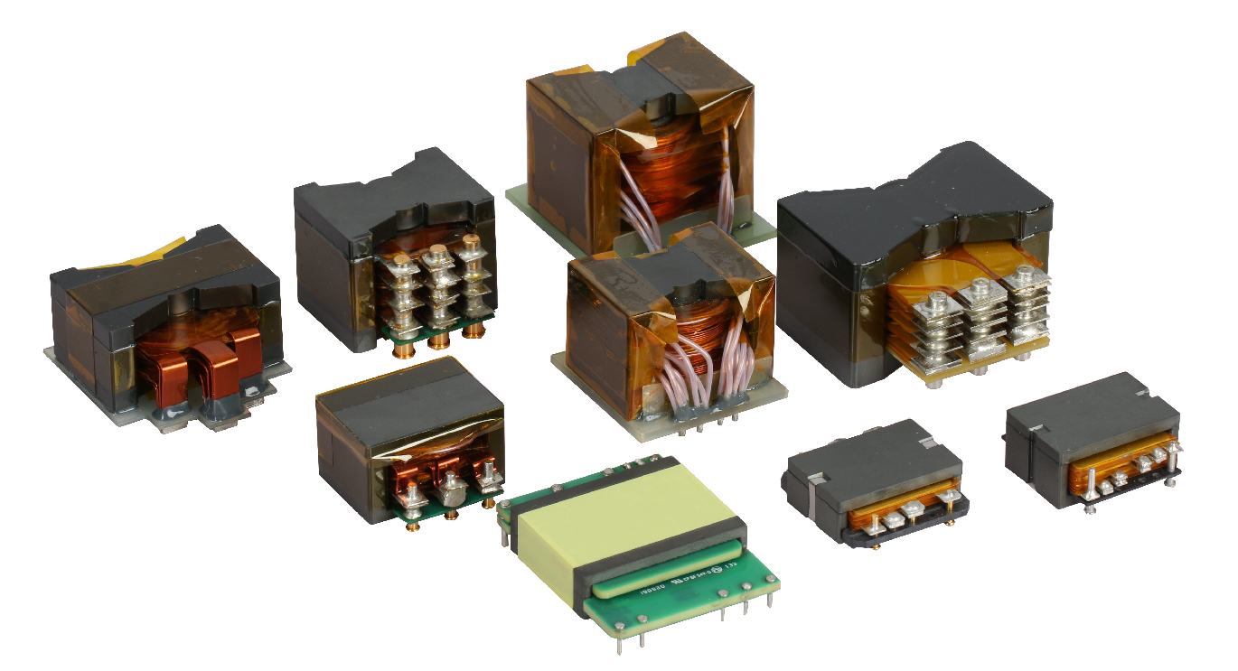
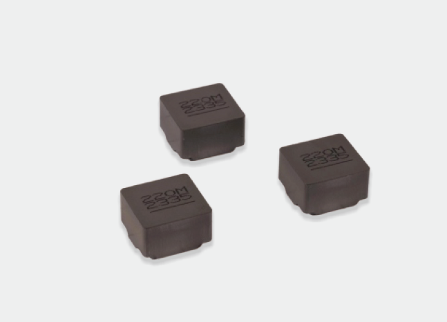
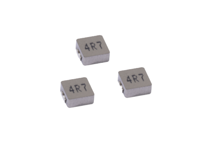
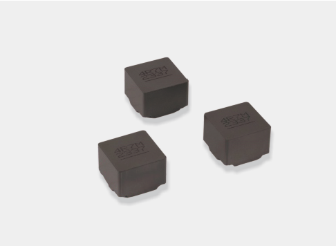
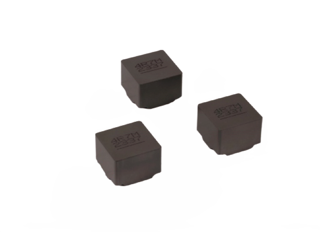
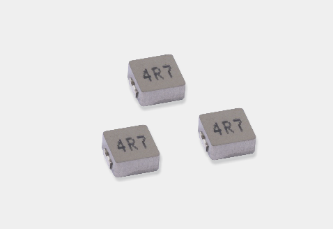
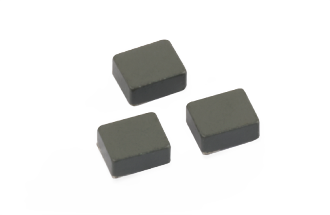
Molded Inductor
Read More
➜
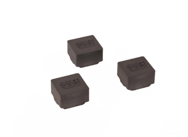
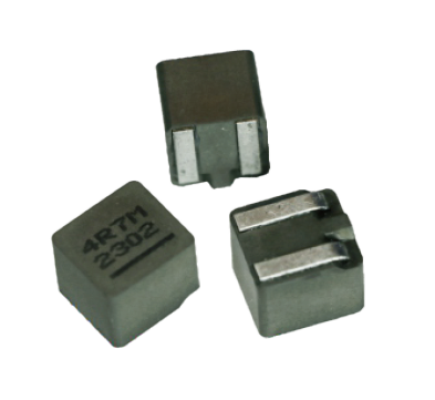
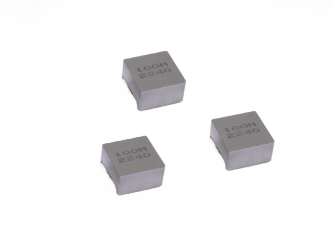
Molded Inductor
Read More
➜
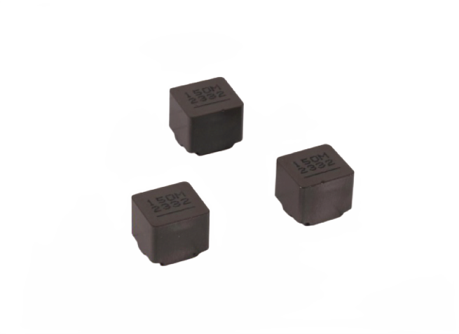
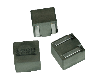
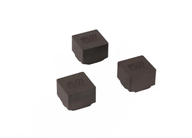
Molded Inductor
Read More
➜
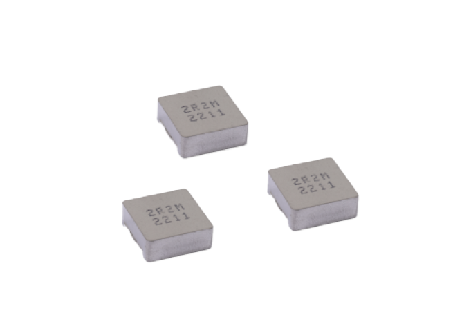
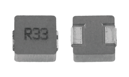
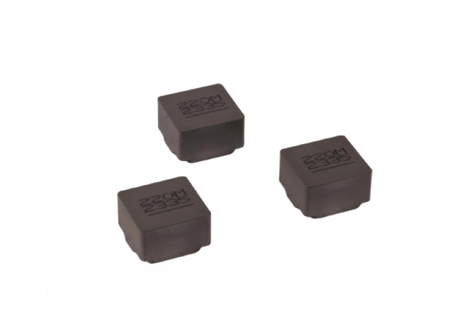
Molded Inductor
Read More
➜
Molded Inductor
Read More
➜
Molded Inductor
Read More
➜
Molded Inductor
Read More
➜
Molded Inductor
Read More
➜
Molded Inductor
Read More
➜
Molded Inductor
Read More
➜
Molded Inductor
Read More
➜
Molded Inductor
Read More
➜
Molded Inductor
Read More
➜
Molded Inductor
Read More
➜
Molded Inductor
Read More
➜
Molded Inductor
Read More
➜
Molded Inductor
Read More
➜
Molded Inductor
Read More
➜
Molded Inductor
Read More
➜
Molded Inductor
Read More
➜
Molded Inductor
Read More
➜
Molded Inductor
Read More
➜
Molded Inductor
Read More
➜
Molded Inductor
Read More
➜
Molded Inductor
Read More
➜
Molded Inductor
Read More
➜
Molded Inductor
Read More
➜
Molded Inductor
Read More
➜
Molded Inductor
Read More
➜
Molded Inductor
Read More
➜
Molded Inductor
Read More
➜
Molded Inductor
Read More
➜
Molded Inductor
Read More
➜
Molded Inductor
Read More
➜
Molded Inductor
Read More
➜
Molded Inductor
Read More
➜
Molded Inductor
Read More
➜

Service Tel
(86-28) 86082899-2805
Copyright © 2026 ZG Tianxin. All Rights Reserved. 蜀ICP备2023041398号-1